Larger versions of most illustrations may be seen by right-clicking them
and selecting an option to view them separately, or by double-tapping and/or
stretching them.
¶ A Book for Boys
Describing and
Explaining in Simple
Language the Automobile
Gas Engine.
By FAY LEONE FAUROTE, B. S. [M. E.] (Former Instructor Detroit Motor School)
Published by the Author
LANSING, MICHIGAN, U. S. A.
Copyright by Fay Leone Faurote
1908
ROBERT SMITH PRINTING CO.
CHICAGO—LANSING
PREFACE
Knowing that the motor car is fast becoming the
modern form of transportation, both in the social
and commercial world, and feeling that the principles
of the mechanism which constitutes its propelling
power are as yet somewhat of a mystery
to the average individual and to “Young America”
in particular, the author feels that some of
the simple explanations offered in the following
pages of this book will be welcomed and appreciated.
While they do not cover the entire subject,
it is hoped that they may tend to shed some light,
and in a way make understandable the construction
and operation of the automobile gas engine.
FAY L FAUROTE.
November 25, 1907.
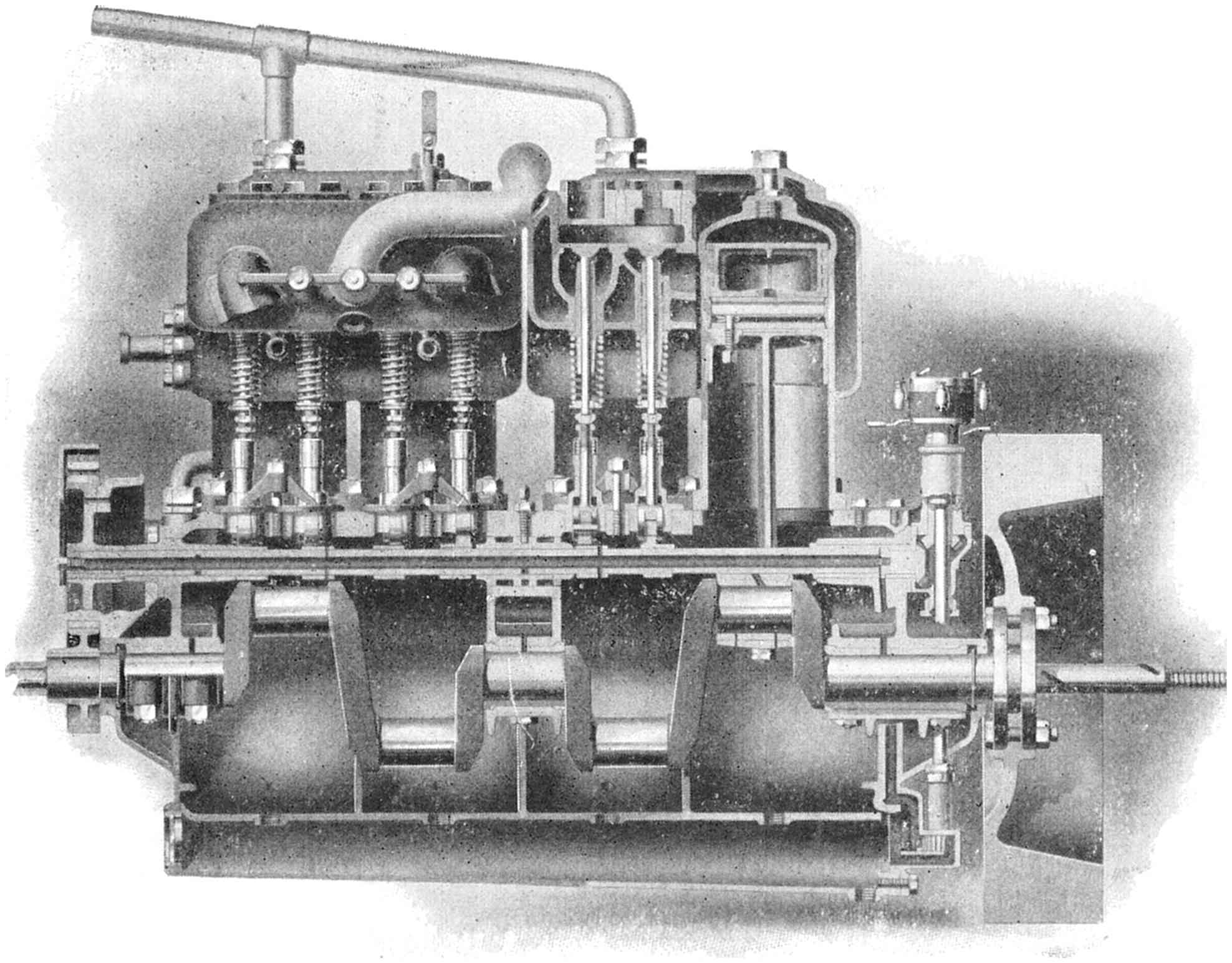
A Four-cylinder Motor, so sectioned that it shows interior of cylinder, valves, piston,
crank shaft and connecting rods.
A BOY’S TEXT BOOK ON GAS ENGINES — INTRODUCTION
Boys, when I was a small boy, I remember how
much I was interested in everything which was
mechanical. The engineer was my hero; the solving
of the mysteries of an engine and the learning
how to drive one, was my ambition.
I remember well how I tried to read the dry,
technical description of motors, steam engines and
such things. I remember, too, how hard it was
to understand those books; how the various technical
terms used to bother me, until at last, in despair,
I would throw the books aside. It seemed
as if the men who wrote them never realized that
boys existed,—that boys wanted to know about
such things.
At other times how glad I was when I found a
good-hearted engineer who seemed to know and
understand my feelings and my desire to learn.
How easy it was to comprehend his explanations,
because he used homely, everyday things to illustrate
his meaning. He made you forget there was
anything complicated about machinery. He simply
took up one part at a time, and when he had
finished with it, everything was as plain as the
nose on your face.
Boys, then and there I decided that if I ever did
understand some of these seeming mysteries of
engineering, I would write a book that boys could
understand. I would write it so that they couldn’t
help it, it would be so plain; there would be no
secrets; they should know all about it, and what
is more, should be able to reason it all out for
themselves.
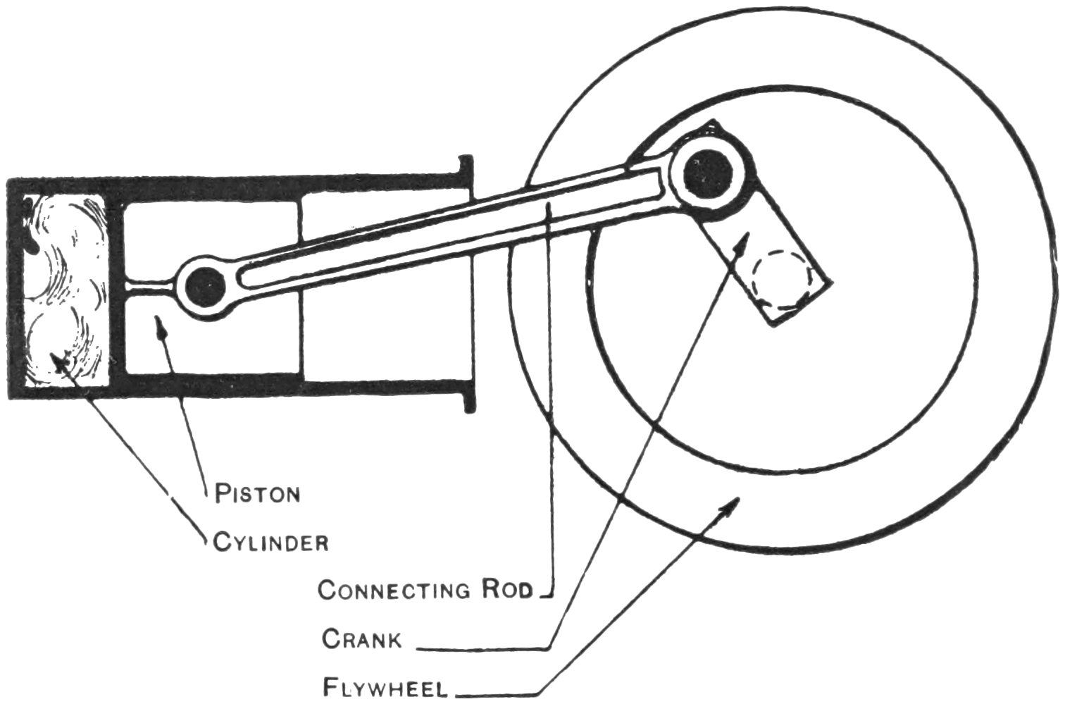
Fig. 1—The Essential Parts of a Gas Engine.
Let me tell you about each part separately.
After we have gone over each part you will find
that you will understand the action of the motor
and other parts of the car well enough so that you
will unconsciously reason it all out for yourselves.
Some of the descriptions and explanations may at
first seem unsatisfactory, but I think with a little
thought and study you will be able to master them
in a short time. I want your confidence, boys, and
then I know we will get along all right together.
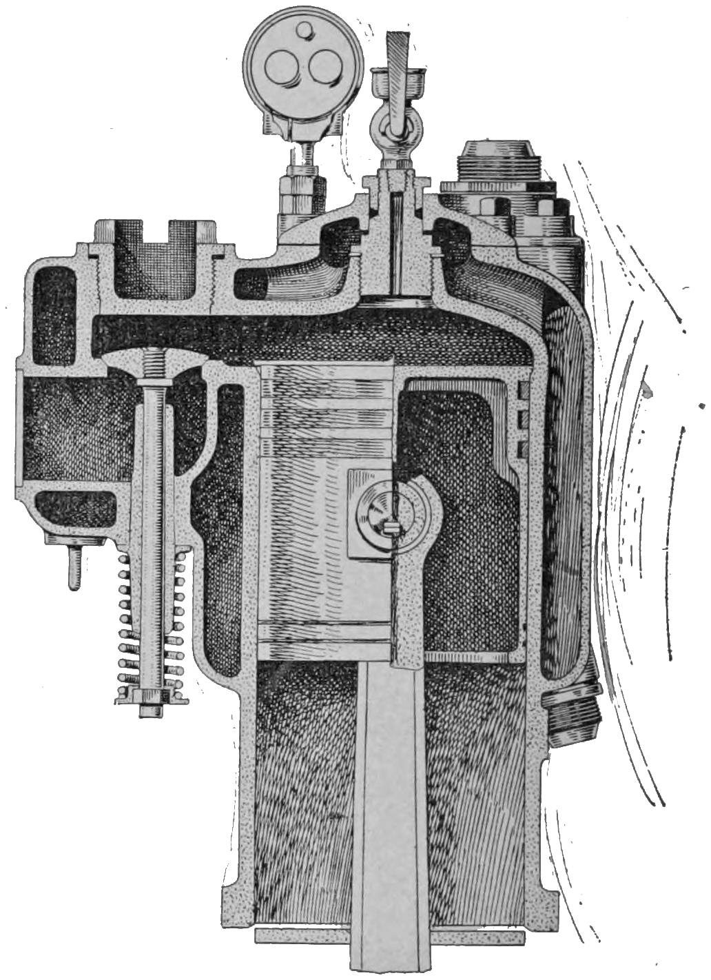
Fig. 2—A Single-cylinder Horizontal Engine. Note location of valves in this type.
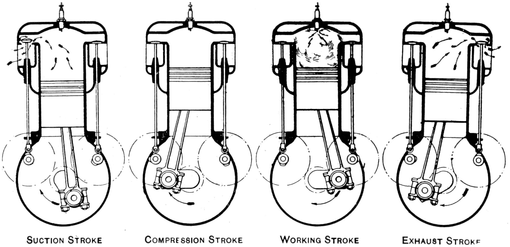
Fig. 3—Four views of a section of a Vertical Cylinder, showing position of valves,
pistons and cams for the four different strokes.
THE FOUR-STROKE CYCLE.
This subject looks like a bugbear, doesn’t it.
Well, it is one of the first things of which we shall
have to dispose, and so we’ll tackle it right away.
We will start backwards, and take the word cycle
first. If you will look in the dictionary you will
find that this word means “a circle or orbit; an
interval of time in which a succession of events
is completed, and then returns in the same order.”
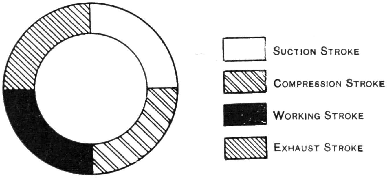
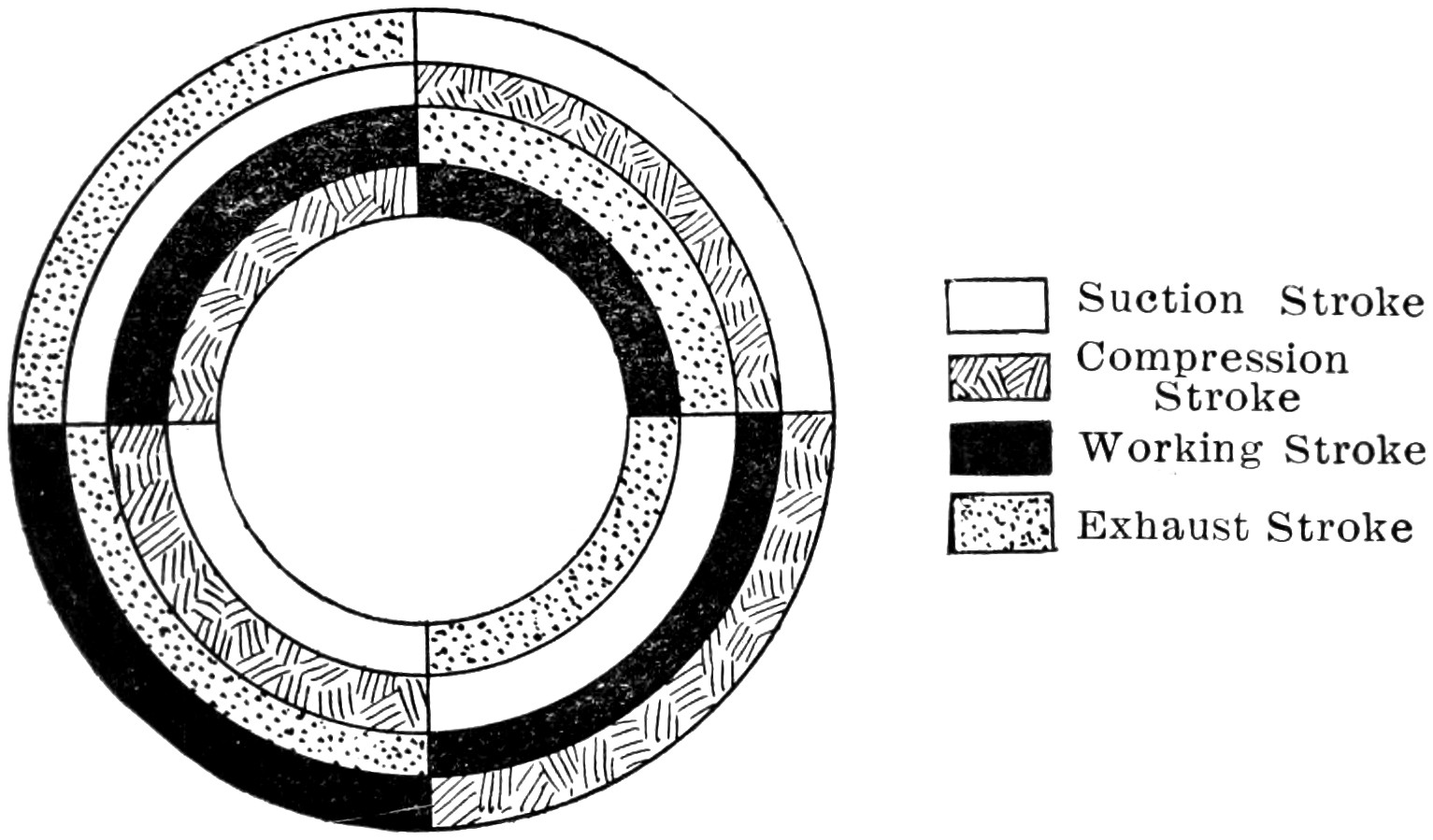
Suction Stroke Compression Stroke Working Stroke Exhaust Stroke
Fig. 4—A Four-cycle Diagram, showing sequence of strokes in this type of
motor.
This does not mean very much to you, does it?
Well, let us go into it a little farther. Supposing
you were running relay races around a block; you
would run down on one side, across on another,
back on the other side, and then back to the starting
point, wouldn’t you? You would have completed
a cycle then because you have taken a “certain
time in which a succession of events (streets)
has been completed” and you are back again at
the start ready to “return in the same order.”
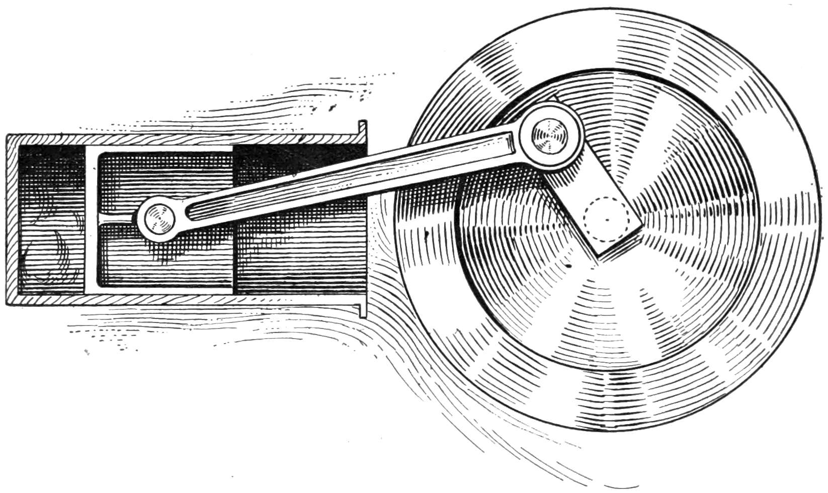
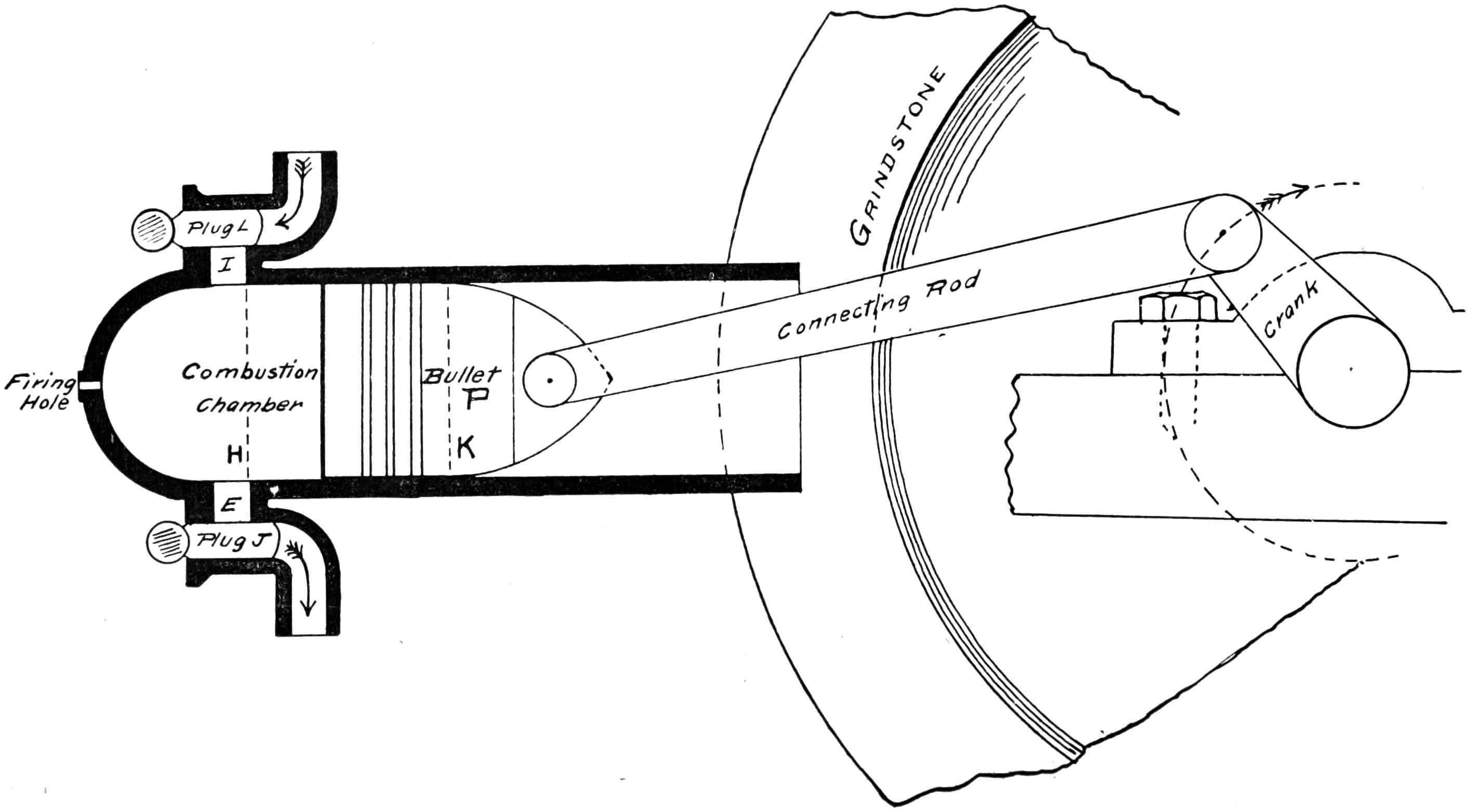
Fig. 5—Drawing showing comparison between gas engine and a cannon connected with a grindstone.
There is not anything complicated about that, is
there? In other words just change the four-stroke
cycle to a four-street circle, and this will help you
to keep in mind the meaning of this term. Do
you remember last Fourth of July when you had
your cannon out, how many things you had to
do to fire it, or in other words to complete the
cycle of operations. You did four things, didn’t
you?
No. 1. You put in the powder.
No. 2. You rammed it in with a ramrod.
No. 3. You fired it by touching a match to it.
No. 4. You cleaned it out.
You had gone around your four-sided circle, and
were back again, at the start, ready to do the
same things over again. You were running a gas
engine then, only you did not realize it.
Let us assume for the sake of argument, that
you had a bullet in your cannon, and that to this
bullet was connected a rod which had its other
end fastened to the crank of a grindstone. Then
if the barrel of the cannon was long enough, and
the rod which connected the bullet and crank was
short, the bullet could not get out of the cannon
barrel, could it? It would therefore have to go
back and forth very much like the pedal on a
grindstone does. Of course the rod and the crank
would have to be very strong in order to keep
the bullet in, but we will assume that they are,
and that the bullet must travel back and forth inside
the barrel. Now, if the bullet is going to
stay in the barrel we must provide some way to
load the cannon, and also to clean it out, therefore
we will cut two holes in the end, one at I
and one at E, and then instead of using powder
suppose you use some explosive gas which will
not leave so much soot behind it. You know how
a squirt gun works—how you draw the water in
by pulling out the plunger, and how you force the
water out again by pushing it in again.
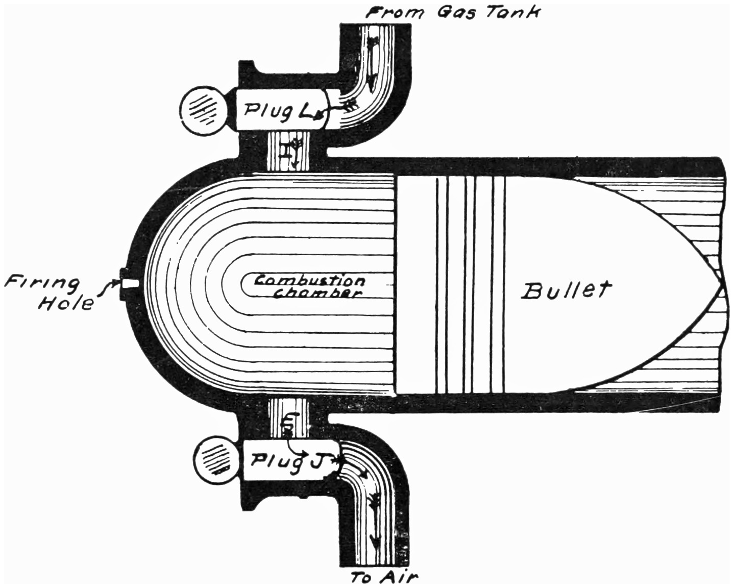
Fig. 6.
Let us work the cannon the same way. Let us call the
farthest point to which the bullet travels going in
“H” and the farthest point to which it travels
going out “K.” Now let us assume that the bullet
is at “H,” and that it is just starting out in
the direction of “K.” If we open the hole “I”
in the side of the cannon by taking out the plug
“L,” and put a hose, connected with our gas tank,
in there, then the outward motion of the bullet
“P” will pull the cannon full of gas, won’t it?
Before the gas has a chance to escape we will
put in the plug “L” again. Now we have the
cylinder full of gas, but as the bullet is at the
end of its stroke, and cannot go any further, we
will have to push the gas together again and get
the bullet into position “H.” This will be a good
thing for the gas, because it will crowd the particles
of it closer together, and make it explode
quicker, so we will do this. Of course, in order
to keep the gas in there we have had to close up
the touch-hole of the cannon, but now that we are
ready to fire it, we will take this plug out, and
touch a match to the gas. An explosion follows,
and the bullet travels from the position “H” to
the position “K.” All this time the crank of
the grindstone must have been turning because
the bullet and the crank are fastened together,
and therefore, instead of traveling through the
air, the bullet has used up its energy in turning
the grindstone. When you get a grindstone
started it is rather hard to stop, isn’t it? And
if you didn’t stop it, it would keep on turning
around, wouldn’t it? If this is true, we might
as well let it clean the cannon. As the hole
“I” is connected with the gas tank, we cannot
let it force the burnt gas out there, can
we? We will therefore pull out the plug “J”
in the hole “E” just as the bullet reaches the
point “K” so that in coming back it will force
the burnt gases and smoke out through the hole
“E.” Now we are all ready to start over again;
the cannon has been cleaned out, and the bullet
still being fastened to the grindstone, which is
turning, as a result of the explosion, would immediately
begin starting out on another outward
stroke. If we put in the plug “J” again and
pull out the plug “L,” the bullet or piston as we
might call it now, will suck in another charge of gas.
Fig. 7—Grinding a valve.Fig. 8—A section of a Cylinder showing
location of various parts—end view.
You can see that if you had two boys, one
of them to pull out the plugs, and another to fire
the charge you could keep the gun firing steadily,
and run the grindstone. After you have done this
for a while you will get tired of taking out the
plugs and putting them in, and standing there
with a match lit all the time, and you would wish
there was some way to make the grindstone, which
was running, do all this for you. This is exactly
what happened to some of the old engineers, and
so they set about trying to accomplish this result.
They succeeded in rigging a piece of machinery
that would open and close these holes
automatically, and with the introduction of electricity
they also devised a way whereby the charge
could be ignited by an electric spark instead of
a match. The plugs which cover the holes, they
called valves and the plug which contained the
electric wires, used for firing the gas, they called
a spark plug.
Now let us see what we have learned in this
chapter. We have found that it takes four strokes
to explode one charge of gas
1. Suction stroke, during which the gas is
sucked into the barrel of the cannon, or cylinder
as it is called.
2. The compression stroke, during which the
gas is compressed so that it will burn easier.
3. The explosive stroke, or working stroke,
called so on account of the fact that the explosive
force of the gas is used to turn the wheel.
4. The cleansing, or exhaust stroke, during
which the burnt gas and smoke is forced out of
the barrel.
For this reason, a gas engine which works on
this principle is called a Four-Stroke Cycle Engine.
It requires four strokes to complete the
entire operation and bring it back to the beginning
ready to start over again.
THE CYLINDER
So far we have confined ourselves to the parts
of a cannon, but now that we are going to take
up the study of the motor in its details let us
call them by their regular names. The barrel of
the cannon we will call a cylinder. In an actual
motor a cylinder is made out of cast iron, carefully
bored out inside, so that the hole is perfectly
round, and the sides of the wall as smooth
as possible.
Fig. 9.
You will realize that this is necessary
as we want to reduce, as much as possible, any
rubbing or friction, as it is called, between the
piston and cylinder walls. Next we must provide
some means of cooling these walls, as you
know that the continuous firing would soon make
them very hot. This is done by surrounding the
cylinder with what is known as a water jacket
through which water can be circulated, thereby
carrying off the heat, and keeping the iron from
getting red hot. We must also cut two holes in
the side of the cylinder to make places for the
valves and a place for the spark plug.
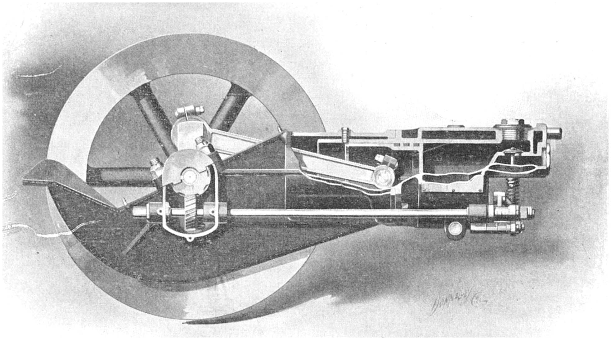
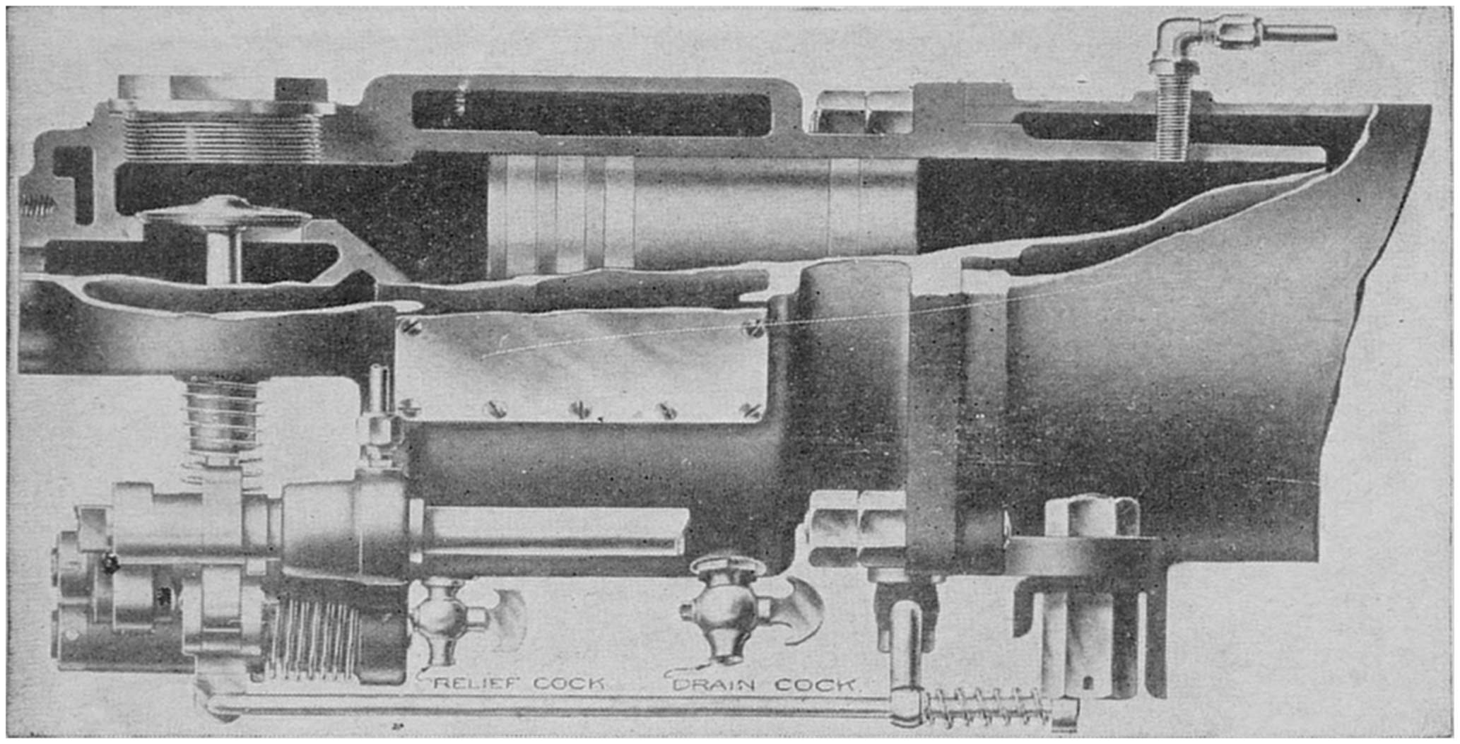
Fig. 10—End view of Horizontal One-cylinder Motor, showing piston, valves
and valve mechanism.
A cylinder is generally mounted on its side in
a one cylinder engine, and is set up on end when
it is desired to use more than one. Therefore, in
a one cylinder motor you will notice that the piston
moves back and forth, whereas in a two-cylinder,
four-cylinder or six-cylinder type, the pistons
move up and down. As far as the action of
the parts is concerned they work in exactly the
same way, only that the valve mechanism has to
be changed somewhat.
The cylinder is bolted to a framework called
the crank case which furnishes a solid foundation
upon which it can rest.
VALVES
You will remember that in first discussing the
drawing in and cleaning out of the gas that two
holes had to be cut in the sides of the cylinder
wall. One of these through which the fresh gas
might be sucked in, and the other through which
the burnt gas might be expelled. Also remember
that we kept these holes plugged except when it
was necessary to have them open to perform their
work.
Fig. 11—The evolution of a Valve.Fig. 12—A regular Valve.
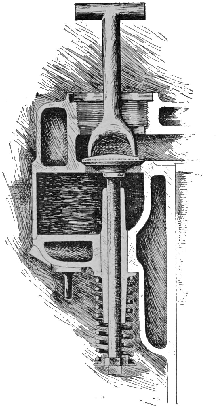
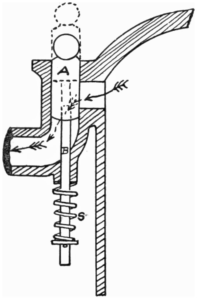
Now let us take a section of a valve and see
how it is made up. You will notice first the little
plug “A” which covers the hole in the cylinder;
it is tapered very much like a glass stopper in
a bottle for the reason that in this form it is
easier to fit it to the opening; it can be “ground
in” in the same way that a glass stopper can, in
order to make an air-tight fit. “B” is a rod
known as the valve stem, and is simply a round
piece of steel fastened to the valve plug “A.”
“S” is a valve spring which holds the valve down
into the cylinder wall, or valve-seat, as it is called.
In order to open these valves you can see that
all that is necessary for you to do is to push up
on the valve stem “B.” This will raise the valve
“A” away from its seat into the position shown
by the dotted lines, leaving a space all around
through which the gas may enter or leave. In
an actual motor, however, little irregular pieces
of steel, cut out in general shape shown in Fig.
14 perform the operation of raising the valve.
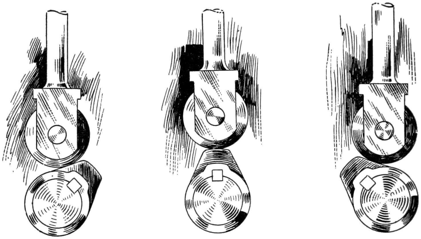
Fig. 13—Three positions of a Valve Cam.
Fig. 13 shows three positions of one of these revolving
pieces of steel, technically called cams,
first, in the act of just starting to raise the valve;
second, its position when the valve is entirely
open; third, its position when the valve has just
closed. If both valves are operated by these cams
you can see that if they are set at the proper position
they can be opened at different times and
entirely independent of each other. If you will
look at Fig. 3 you will see a complete motor, the
inlet valve on the left side, and the exhaust valve
on the right side. This figure will also show you
the little cams in their various positions at different
points of the four strokes. Sometimes
the two valves, instead of being on opposite sides
of the cylinder, are placed on the same side, and
both cams are put on the same shaft, which, by
the way, is called a cam-shaft.
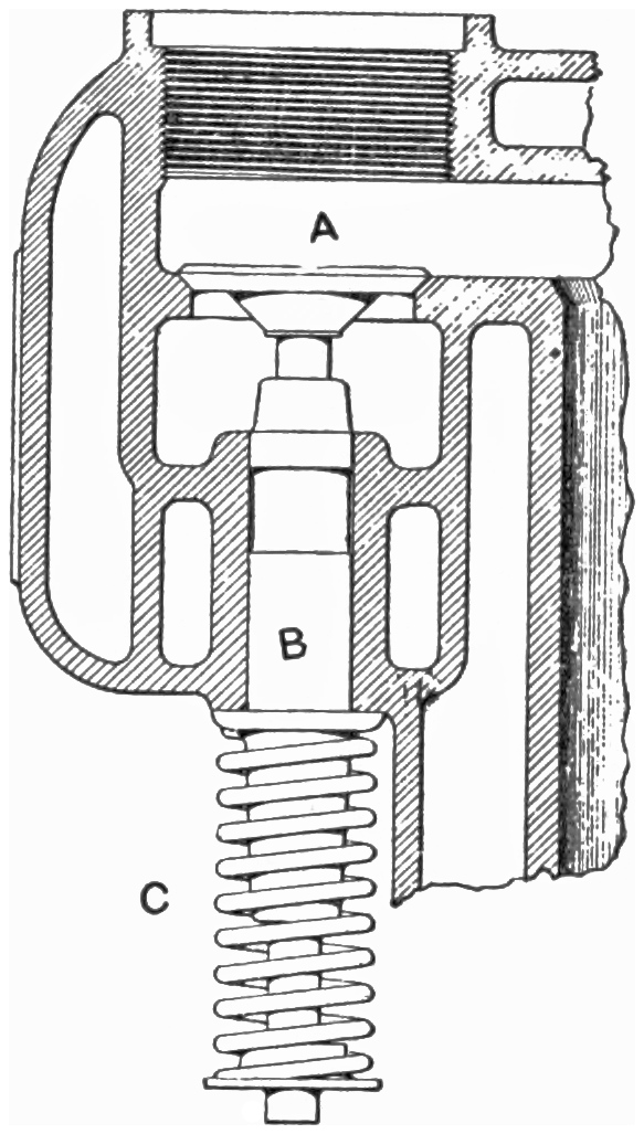
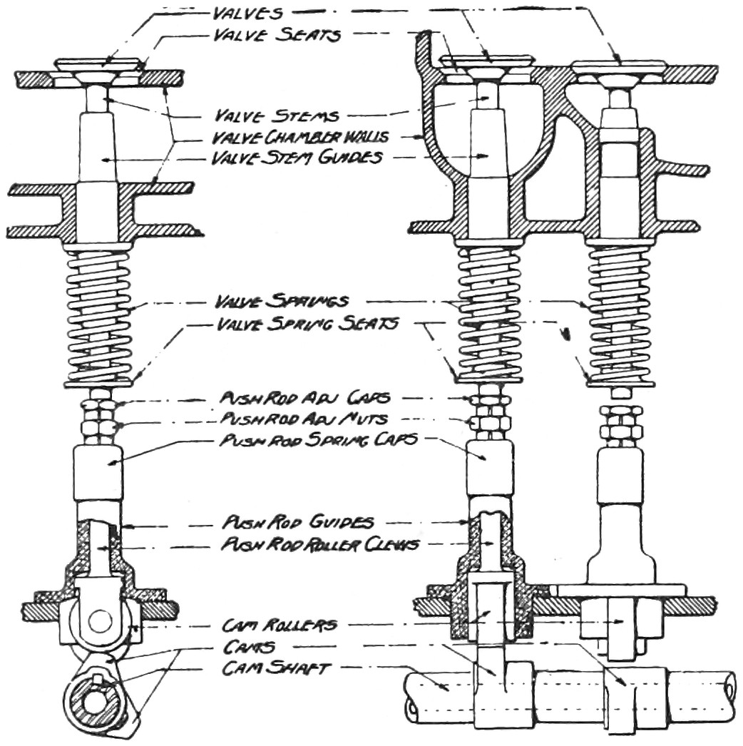
Fig. 14—Names of Valve Parts.
Fig. 14 shows two such valves, the left hand
one opening, and the right hand one closed. The
extreme left hand view shows the way they would
look if viewed from the end. It also gives you
the names of all the parts.
Fig. 7 shows how the valves are “ground in.”
The way you do it is to take the valve out, and
coat it with very fine emery dust and oil, and then
put it back in place leaving off the spring, fit
a wrench to it on top as shown in the picture
and twirl it around as you would a glass stopper
in a bottle until it is perfectly air-tight, after
which the valve should be removed and both it
and the valve seat carefully wiped off so that none
of the emery will get into the cylinder or other
working parts of the engine and cause them to
be cut.
There are several different ways of making
valves and several places to put them so that you
must not always expect to find them in the same
place. Their action is the same, however, no matter
where they are situated or how they are operated,
and I think with a little examination and
study you will always be able to find them and
understand how they work in any engine.
THE PISTON
The piston forms, as you will recall, the bullet
in the cannon, which instead of leaving the barrel,
was made to travel back and forth inside of
the cylinder under the action of the explosive gas.
Owing to the fact that a solid piece of iron would
be very heavy and would get very warm, the real
piston used in a motor is made hollow so that
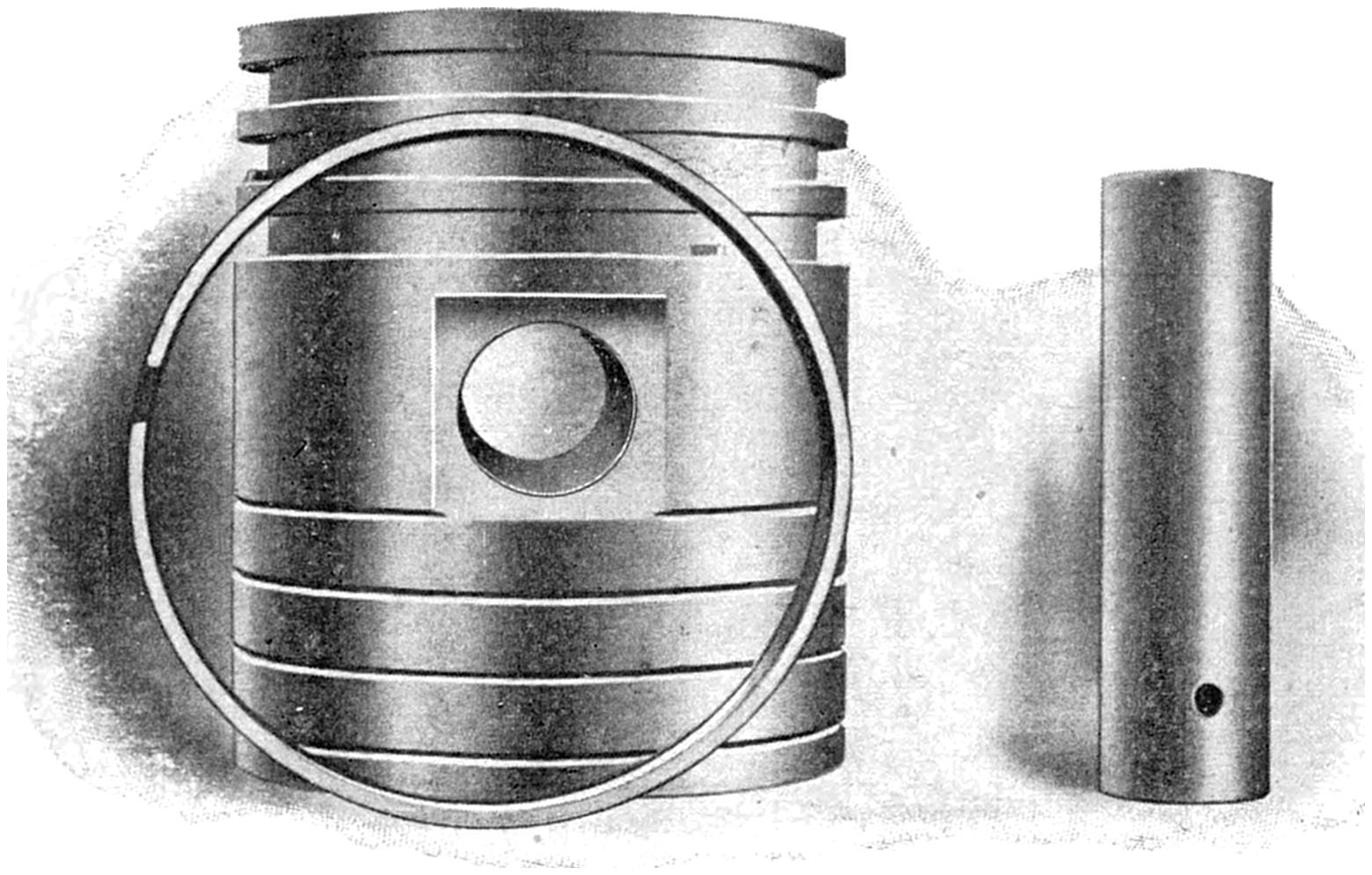
it is merely a shell. Instead of fastening the rod
to the end of it, a small rod, called the piston pin
is in the center of it, and to this the connecting
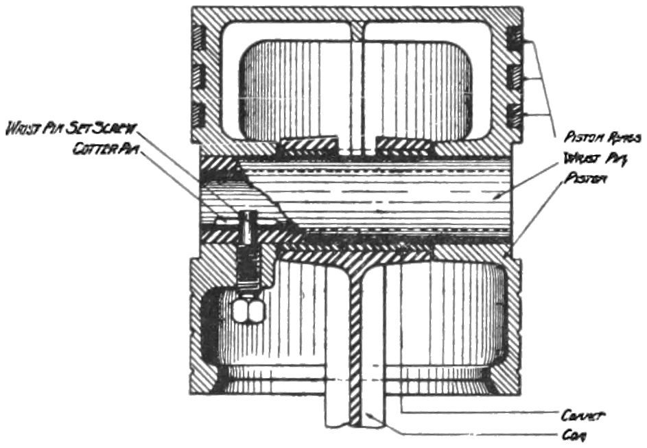
rod is connected. Fig. 16 shows a section of the
piston. You will notice that the piston pin is
kept from sliding sideways by a bolt that is
screwed into it.
Fig. 15—A Piston, Piston Ring, and Piston Pin.
Owing to the fact that both the cylinder walls
and piston get hot, and that iron expands and
contracts according to its temperature, it is not
possible to make a piston alone which would remain
air-tight all the time. Engineers, therefore,
found it necessary to put rings, which were cut
at some point in their circumference, on the outside
of the piston itself. These piston rings, due to
the fact that they are cut, can accommodate themselves
to the varying diameters of the cylinder,
and can therefore keep an air-tight fit, even when
the piston is moving back and forth all the time.
Most of you, no doubt, know that the plunger in
a pump is made air-tight by one or a set of leather
washers, which, owing to their pliable structure,
can expand or contract so as to always fit air-tightly
the pipe in the pump. Piston rings work
in precisely the same manner, and are always kept
lubricated so that they will work smoothly, thus
doing away with any friction which might result.
Fig. 16—A section of a Piston, showing location of piston pin and end of
connecting rods.
THE CRANK SHAFT
Most of you are familiar with a crank as applied
to a grindstone. A crank in a motor is practically
the same shape except that it is supported
on two bearings instead of one and is therefore
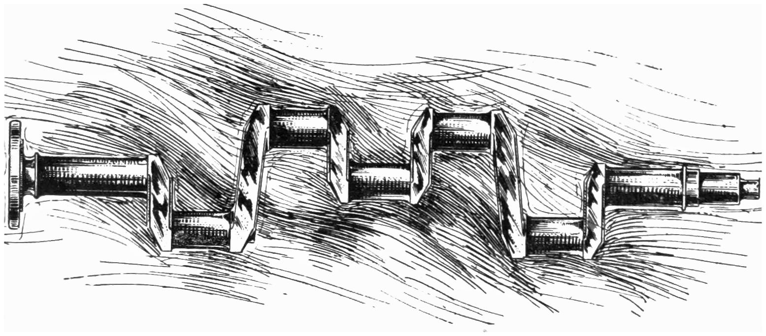
made in the form shown in Fig. 17. The crank
shafts for two and four-cylinder motors are only
a combination of two or four of these single
cranks. Crank shafts are made up of steel, carefully
forged, and then turned and ground down to
proper size to fit the bearings for which they are
intended. They are hardened and every precaution
taken to keep them from wearing. They
form one of the most important parts of the motor
because they change the back and forth motion
of the piston into the rotary motion of the fly
wheel. The fly wheel in our former illustration
was represented by the grindstone itself. In the
real motor the fly wheel is made of cast iron, and
after being carefully balanced so that it turns
evenly, it is securely bolted to the crank shaft, so
that they practically form one piece.
Fig. 17—A Four-cylinder Crank Shaft.
THE CONNECTING ROD
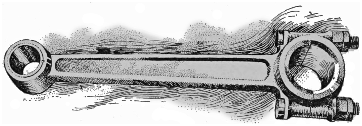
The connecting rod, as you can guess from its
name, forms the connecting link between the piston
and crank shaft, transferring the energy of the
explosive gas, acting behind the piston, to the
crank shaft and fly wheel, from which it can be
transmitted to the driving wheels of the automobile.
It is made up in some such form as shown
in Fig. 18 and is made of steel or bronze. It
has a bearing at each end, the smaller one fitting
around the piston pin, the larger one surrounding
a portion of the crank shaft called the crank pin.
Both of these bearings are lubricated by oil which
splashes up from the bottom of the crank case
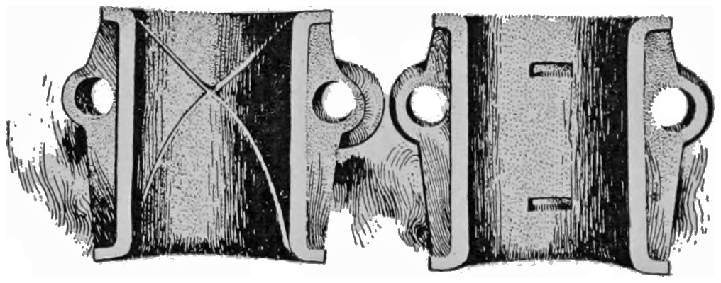
when the engine is running. You will notice that
one of the bearings is cut in two and bolted together
so that you can take it off from the crank
shaft, should you wish to examine it.
Fig. 18—A typical Connecting Rod.Fig. 19—The two halves of the Connecting Rod Bearing.
THE CRANK CASE
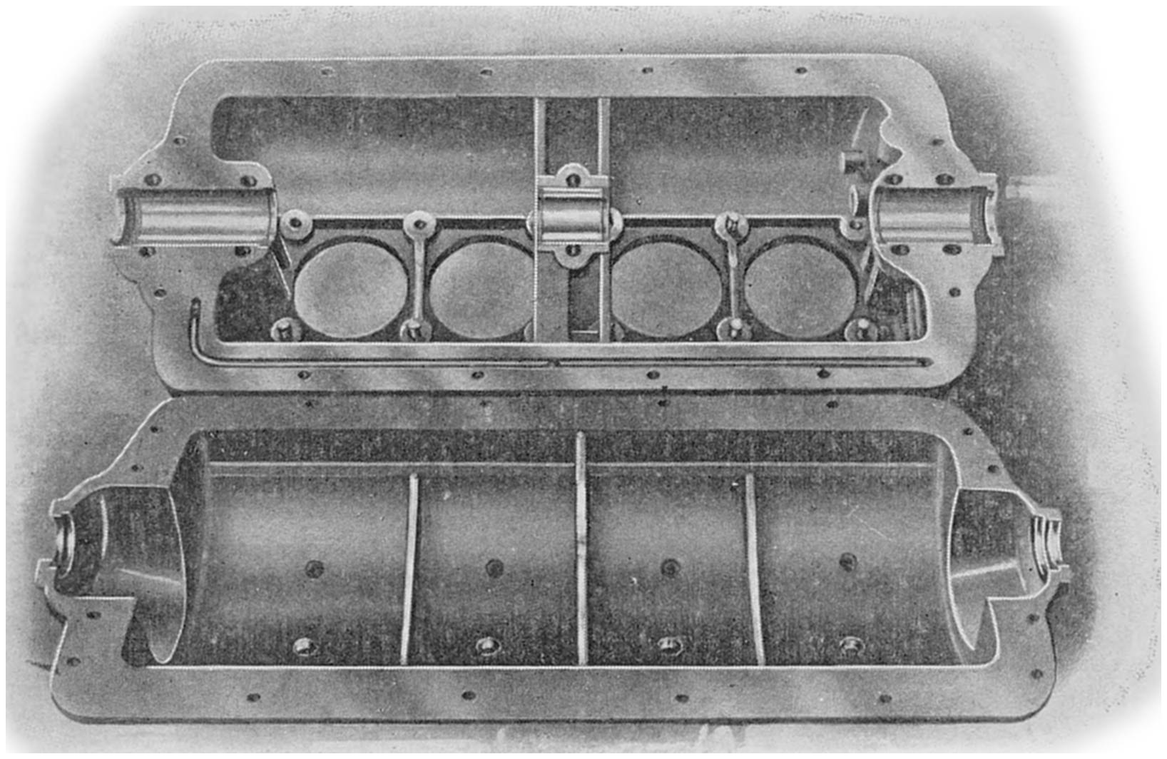
The crank case of a motor serves as a foundation
for the engine, furnishes a support for the main
bearings in which the crank shaft revolves and
encloses the working parts in such a way as to
provide for their lubrication and protect them
from the dust and other substances which might
materially hinder the proper performance of their
functions. To a certain extent the crank case
might be compared to the framework of the grindstone,
although the latter does not answer as many
purposes as the real crank case of the motor does.
Fig. 20—The two halves of a Four-cylinder Crank Case.
The case itself is made of iron or aluminum,
and is so put together that, although practically
air-tight, there is still a means provided for getting
inside of it for examination of the working
parts or an adjustment of the bearings.
THE CARBURETOR
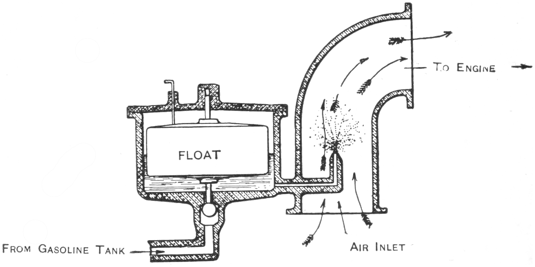
The carburetor or mixing chamber, as it is
sometimes called, is a device used for obtaining
an explosive mixture of gasoline and air. It consists,
as shown by the accompanying drawing, of
two principal parts, an air pipe and gasoline pipe,
the latter running through the wall and discharging
into the center of the former.
Fig. 21—Simple drawing of a Carburetor.
In order to make sure that the amount of gasoline flowing
out of the gasoline jet shall be just the right
amount at all times it is necessary to provide a
little gasoline tank, which forms a part of the carburetor
casting itself, which is known as a float
chamber, so that the amount of gasoline in the
main tank will not affect the amount discharged at
the nozzle. You can see why this is necessary if
you think of a water tank or a dam. If the water
was almost up to the top of the dam and you
should bore a hole through the wall somewhere
near the bottom, the water would flow out faster
than if the water was low. By putting this
little gasoline tank in the carburetor itself and
keeping a certain height of gasoline in this smaller
reservoir, which always automatically shuts
off the supply at the right time, you can make the
pressure, and therefore the flow of the liquid, always
the same. The illustration will show this
plainly. For instance, when the gasoline gets low
the little float will gradually drop down until the
ball on the end of the float stem will open the
valve in the gasoline pipe. The gasoline will then
flow in from the tank until the proper amount has
filled the float chamber and caused the float to
bob up to its former position, carrying the ball,
which closes the gasoline off, up with it. By this
means the requisite amount of gasoline is always
kept in the float chamber.
The amount of air entering the mixing chamber
is controlled by changing the size of the hole
through which the air enters and the quantity of
gasoline admitted is regulated by means of a
needle valve in the gasoline pipe.
Although many carburetors, in fact most of
them, do not look like this drawing, yet their action
is the same, and by careful study you will
find that the same principles enter into their construction.
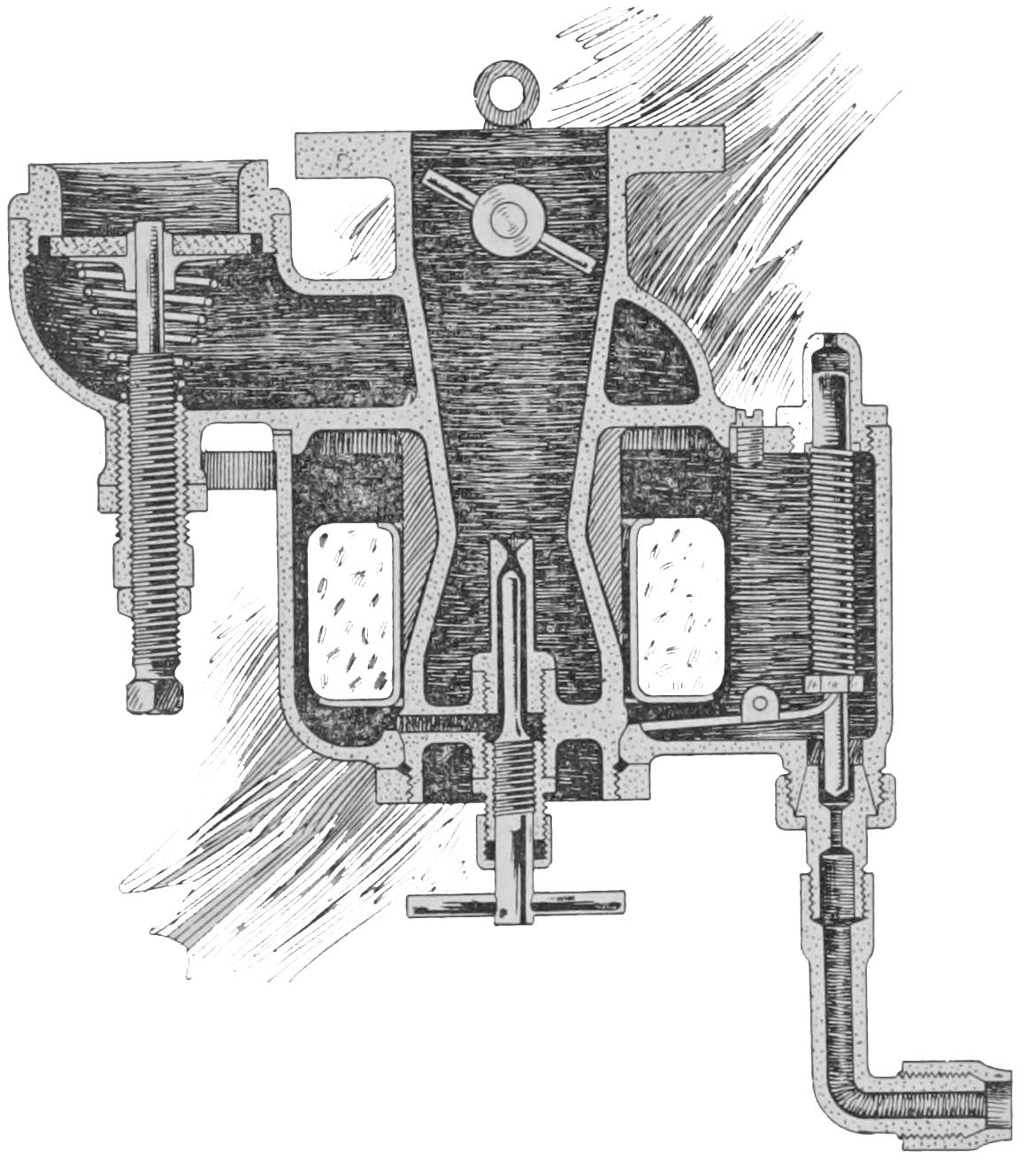
Fig. 22 shows an actual sectional drawing
of a carburetor used on a four-cylinder motor.
In this particular carburetor, however, the float
chamber and float surround the mixing chamber,
and the float valve, instead of being directly under
the float, is at the right hand side and is operated
by means of a lever. The needle valve, which
is the little round rod having a “T” handle, running
up through the center of the mixing chamber,
controls the amount of gasoline flowing from the
gasoline chamber to the nozzle. The air comes
up through the bottom and around the gasoline
jet. At the left you will notice a small valve which
opens downward, which you do not find on the
other carburetor. It is known as an auxiliary
air valve and allows a certain amount of air to
be added to the mixture, a small quantity of which
is sometimes needed to keep the mixture just right.
The throttle valve, which looks like a damper in a
stovepipe and which controls the amount of gasoline
vapor going in to the engine, will be seen in
the upper pipe.
Fig. 22—A Typical Four-cylinder Carburetor.
THE IGNITION SYSTEM
The ignition system is the name applied to the
batteries, coils, commutator and spark plug which,
acting as a whole, produce an electric spark hot
enough and at the right time to fire the charge
in the cylinder. There are three ways in which
an electric current may be obtained which have
been found to be of practical use in automobile
construction. First, by a dry battery; second, by
a storage battery; and third, by magneto or dynamo.
You can look up the construction of these
things in any good book on electricity, so that I
will not explain them further here. As the object
of the whole system is to produce a sufficiently
hot spark to fire the mixture at the right time,
it is sometimes necessary to raise the pressure of
the electric current. When either a dry battery
or storage battery or a certain type of magneto
is used, it is necessary to put it through what is
known as an induction coil in order to raise the
pressure so it will be high enough to jump across
the two points in the cylinder.
An induction coil consists merely of a bundle
of soft wires around which is wound two separate
coils of wire. The first, known as the primary
winding, is of coarse wire, and the second, known
as the secondary winding, is of fine wire. When
the current flowing through the primary coil is rapidly
made and broken, another current of very
high voltage is created in the secondary circuit.
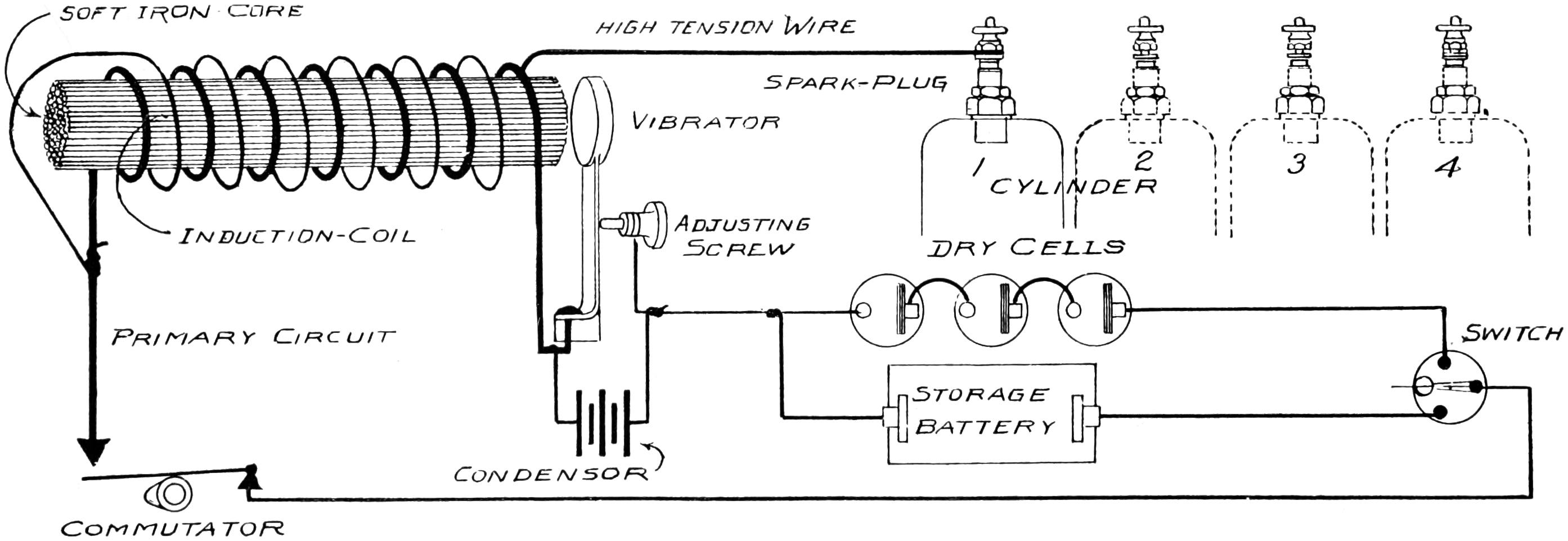
Fig. 23—Wiring Diagram, showing electric circuit for one cylinder. The sketch is only diagrammatic—not a reproduction
of any actual wiring system.
When the current starts to flow through the primary
winding, the bundle of wires immediately
becomes a magnet and attracts the vibrator. As
soon as this occurs, however, the flow of the current
is interrupted and the vibrator resumes its
former position and the action is repeated. Thus
you can see that the coil automatically makes and
breaks its own circuit. The rapidity with which
this is done may be changed at will by adjusting
the vibrator screw.
Fig. 24—The Four-cylinder, Four-cycle Diagram, showing the order in
which the various cylinders do their work.
Having thus obtained an electric current of sufficient
strength to fire the mixture it is necessary
to supply a device which will automatically open
and close the electric circuit at the proper time.
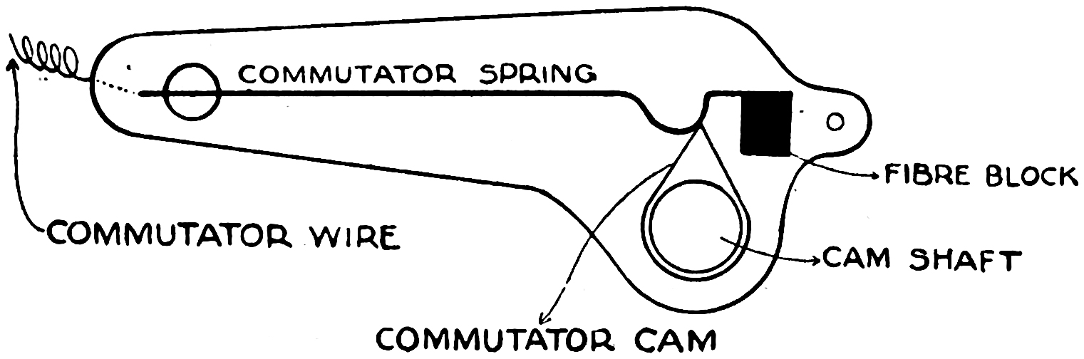
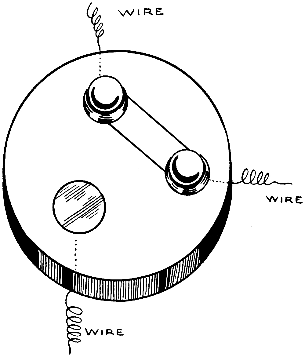
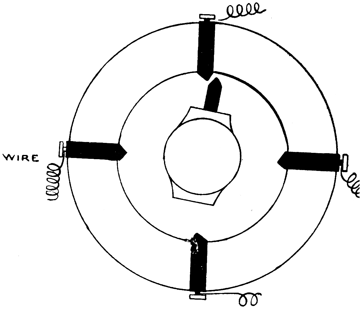
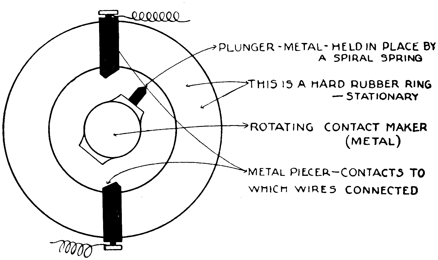
Such a device is called a commutator and consists
of two parts; one a rotating part, actuated by the
engine, which makes a metallic contact with one
or more points on a stationary part, the points being
so located that contact occurs at the proper
time for igniting the charge in any particular cylinder.
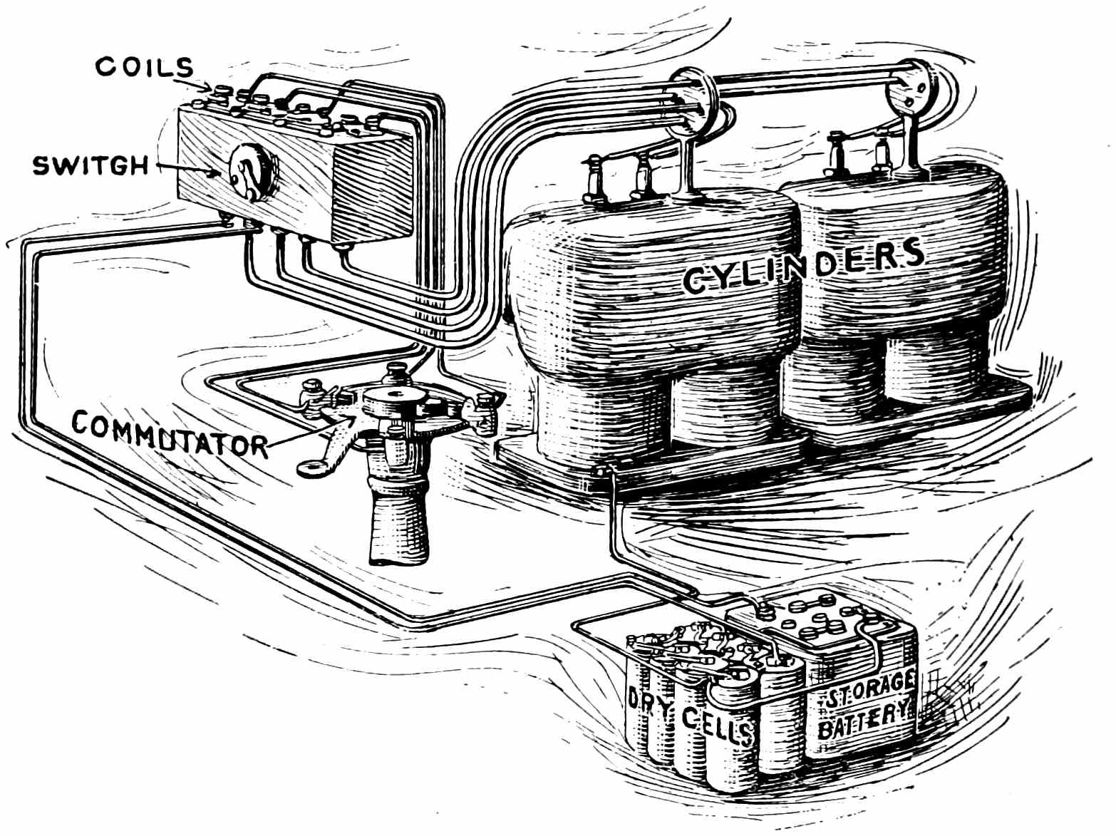
Fig. 25—Four-cylinder Wiring Diagram.
In the four-cylinder wiring diagram (Fig. 25)
various parts of an ignition system may be easily
seen. The electric current is furnished either by
a set of dry cells or by a storage battery. Four
individual coils and a four point commutator are
used. The commutator is driven by means of
bevel gears from the engine itself. A single
switch controls the whole circuit, it being provided
with two points, making it possible for
either battery to be used at will.
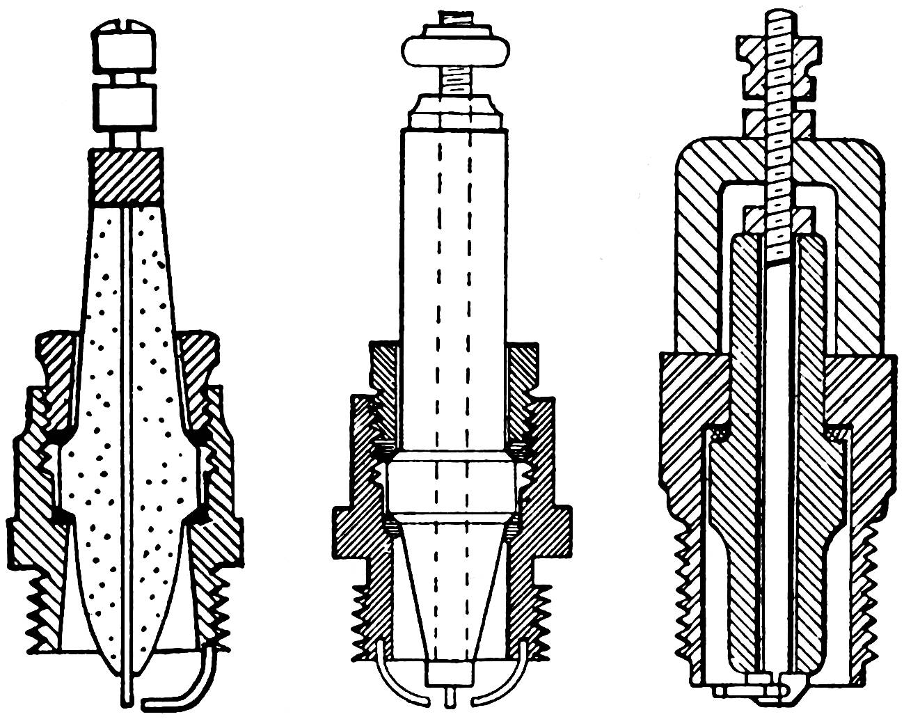
Fig. 26—Types of Spark Plugs.Fig. 27—A Single Cylinder Commutator. Diagrammatic sketch.
In order to prevent the walls of the cylinder
from becoming red hot, it is necessary to cool them
by some means, and this is done by surrounding
the cylinder with a water jacket through which
the cooling water is circulated.
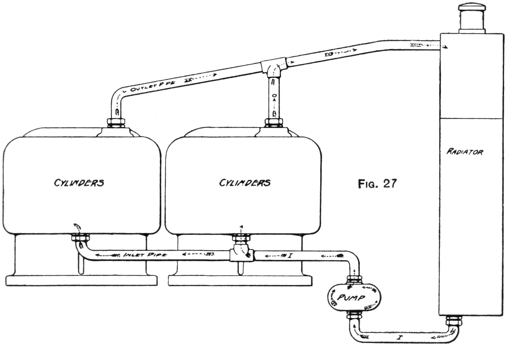
Fig. 31—A Diagram showing piping and direction of circulation
in a One-cylinder Water-cooled Motor.
In order to prevent
the water from boiling and evaporating, thus
making the constant addition of water necessary,
a radiator is introduced into the system. This
radiator is made up of very thin tubes which give
up their heat rapidly, thereby keeping the temperature
of the water below the boiling point. A
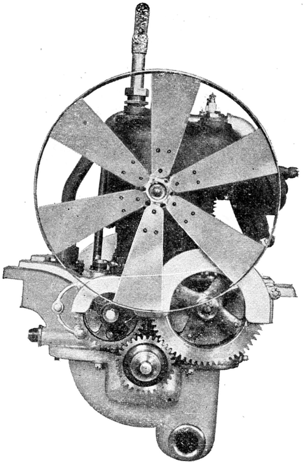
fan is also used sometimes to draw the air through
between the tubes, thereby making the process of
cooling take place more rapidly. The system is
so arranged that the water is drawn from the
lower part of the radiator where the water is
coldest by means of a pump and forced up through
the water jackets and back into the radiator again.
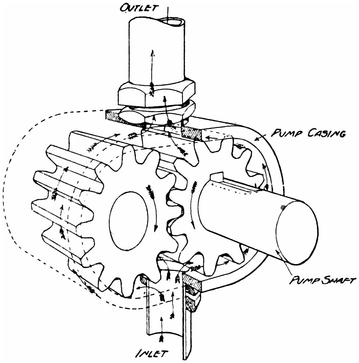
Several different styles of pumps are used, but a
very common one is the gear pump shown in Fig.
32. As you will see by the drawing, it consists
of two gears en mesh with each other which revolve
in the direction indicated by the arrow. The
water entering through the inlet pipe is drawn
around the outside and forced out through the
outlet at the top.
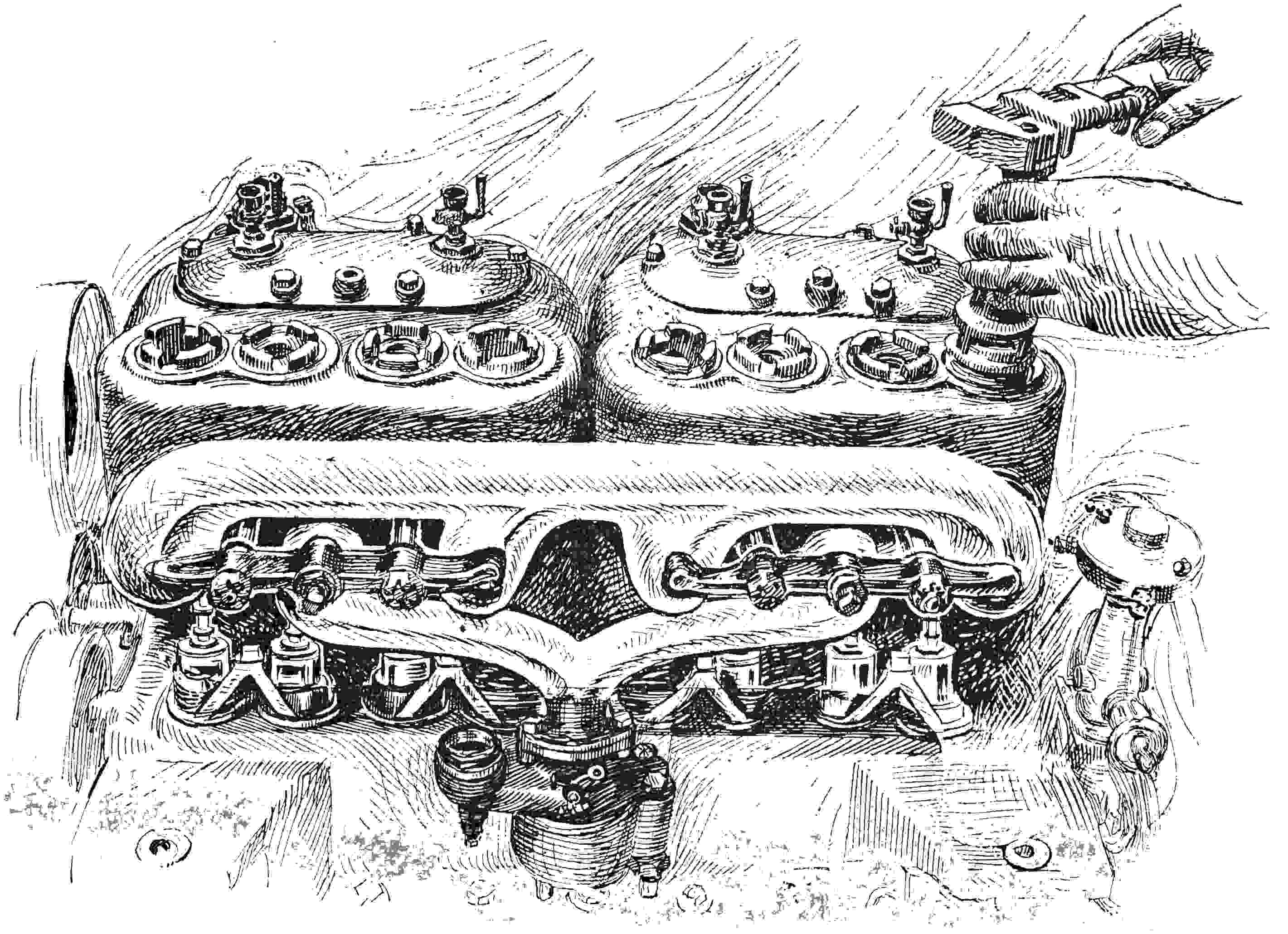
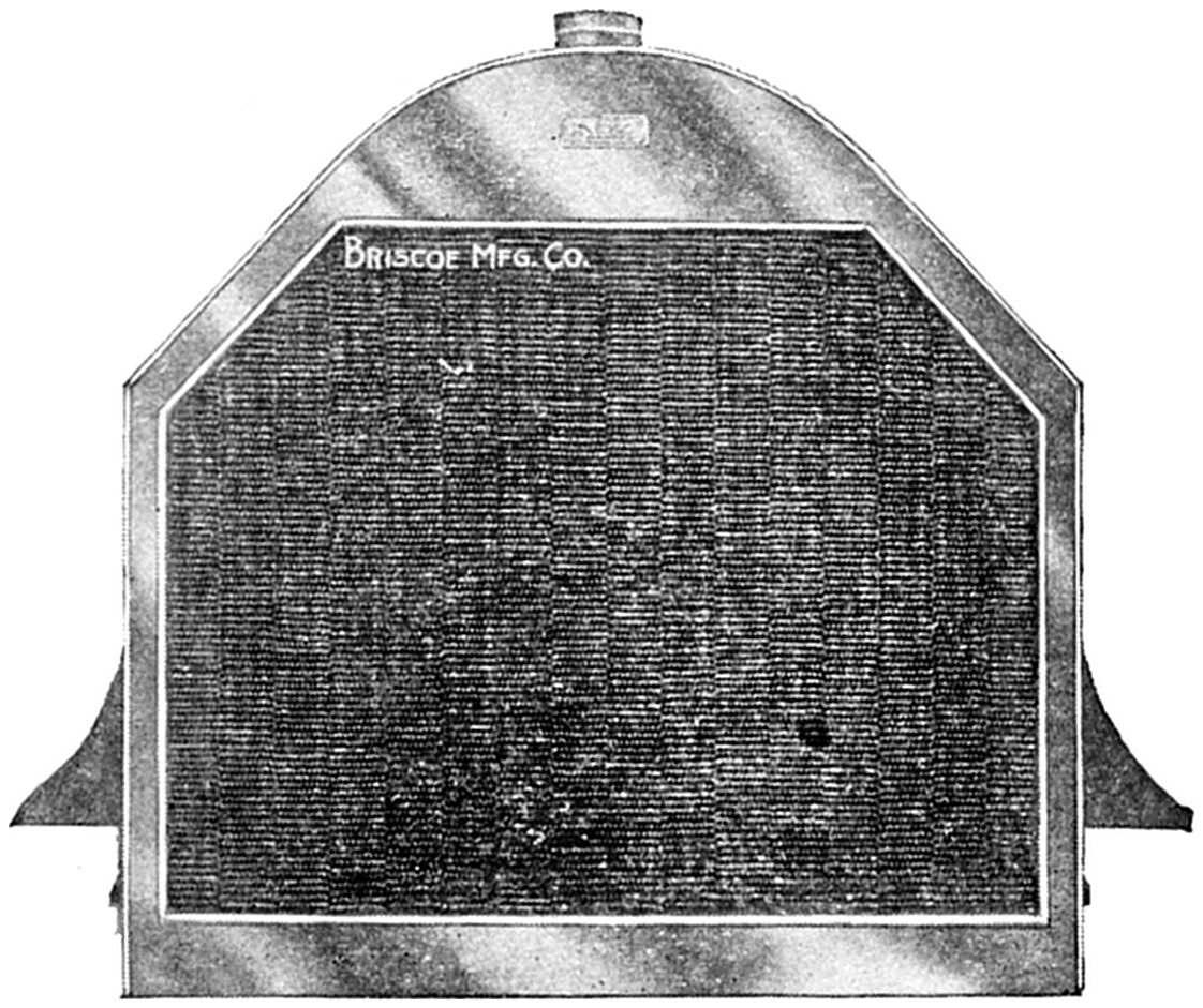
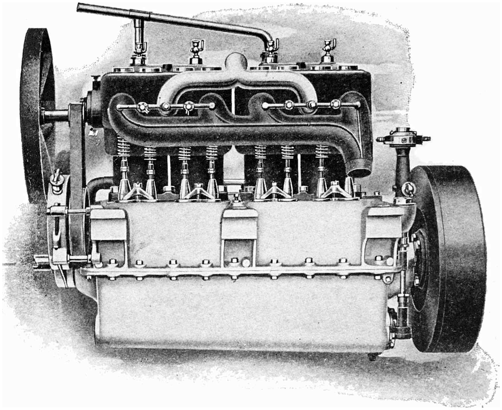
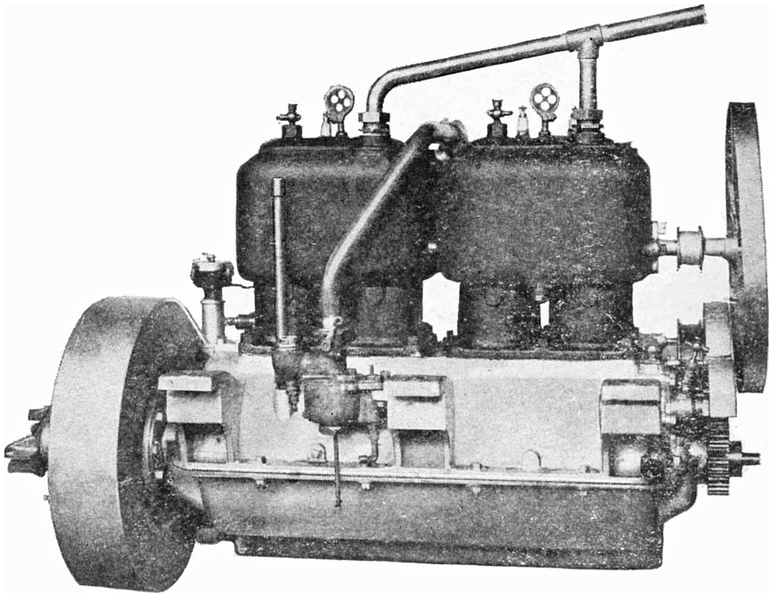
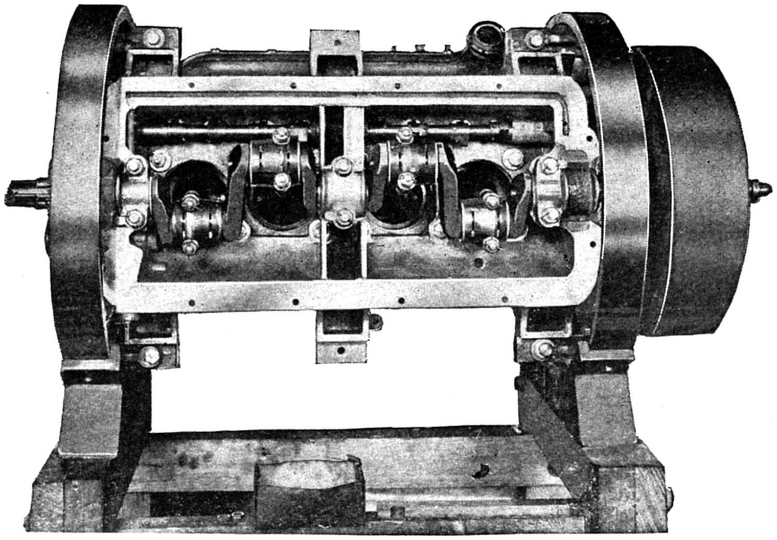
Fig. 32—A Gear Water Pump.Fig. 33—Front End of Motor, showing radiator, fan and cam shaft gears.Fig. 34—A typical Radiator.Fig. 35—Valve side of a Four-cylinder Motor.Fig. 36—Opposite side of same Motor showing Carburetor and Inlet Pipe.Fig. 37—Bottom view of same Motor with oil pan removed showing Crank
Shaft, and Connecting Rods.
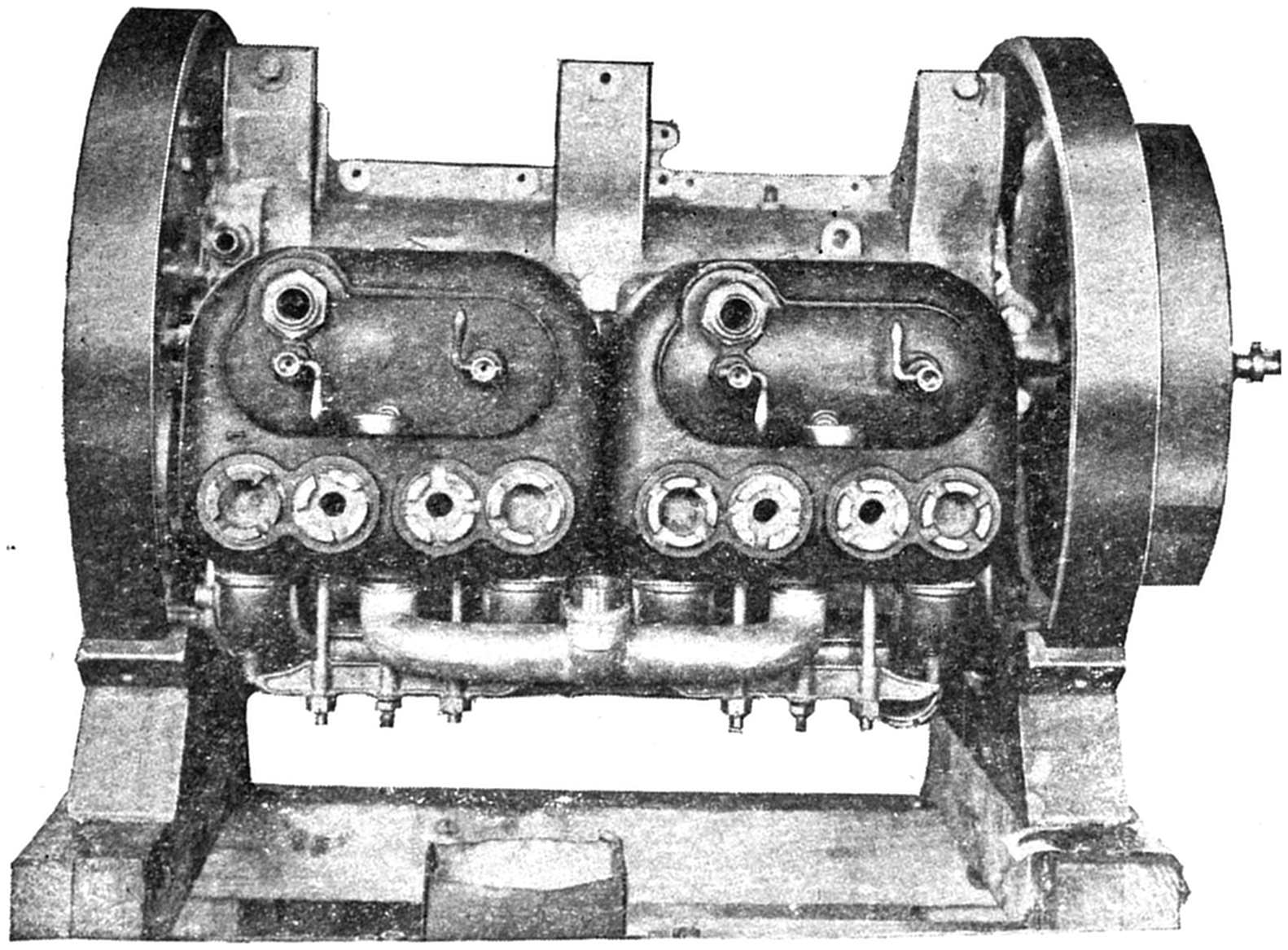
Fig. 38—Top view of same Motor showing Valve Caps and Holes for Spark
Plugs.
NOTE—Both views show motor mounted in ring frames used for assembling
in factory.
THE TWO-CYCLE MOTOR. — INDEX — Transcriber’s Notes
Although the four-stroke cycle type of motor is
used by most of the automobile manufacturers, yet
there is another type which has given such good
results that it is destined to become one of the
important forms to be used in gas engine vehicle manufacture.
Fig. 39.
It therefore merits a brief description.
It has the advantage of being very simple in
construction and operation, and for this reason
it has become very popular among the marine
engine builders, although with a few exceptions it
has not as yet been accepted by motor car engineers.
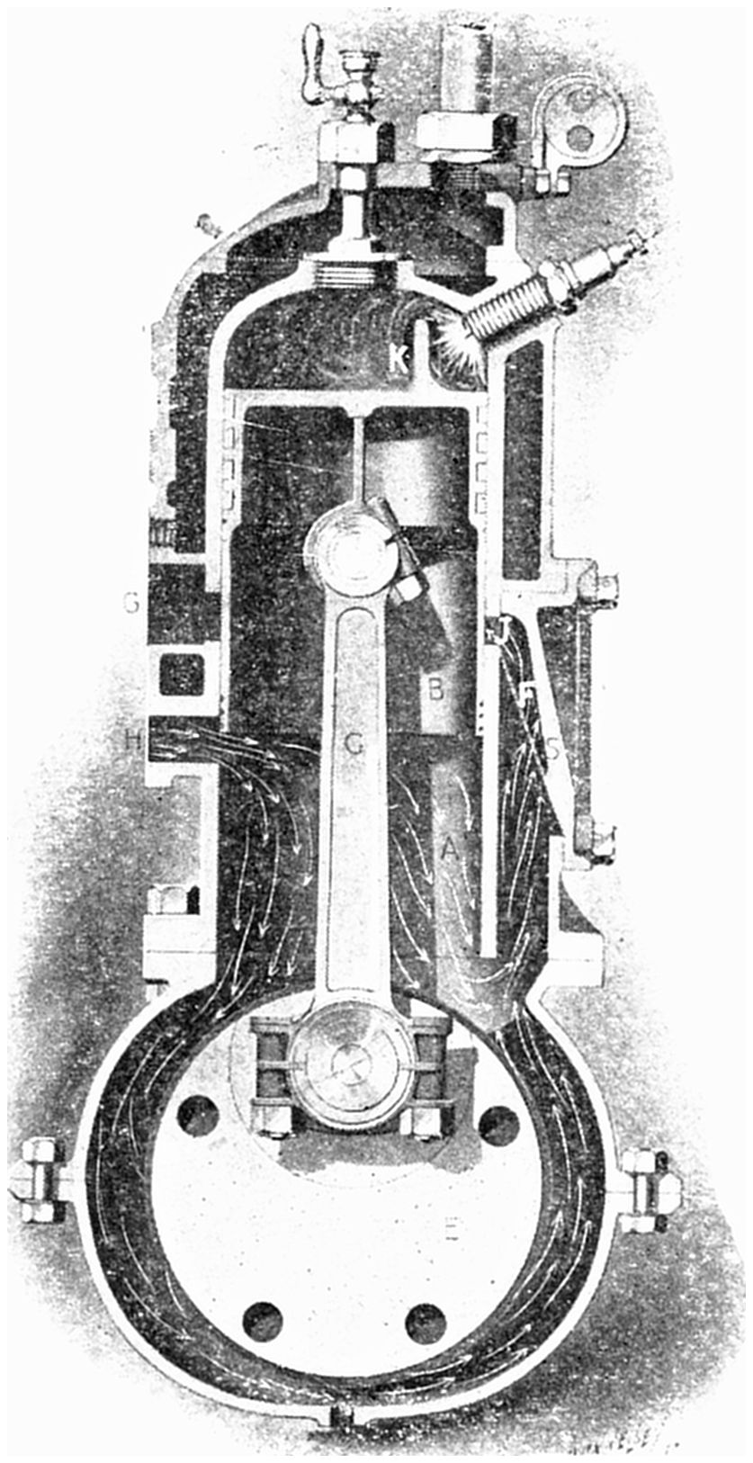
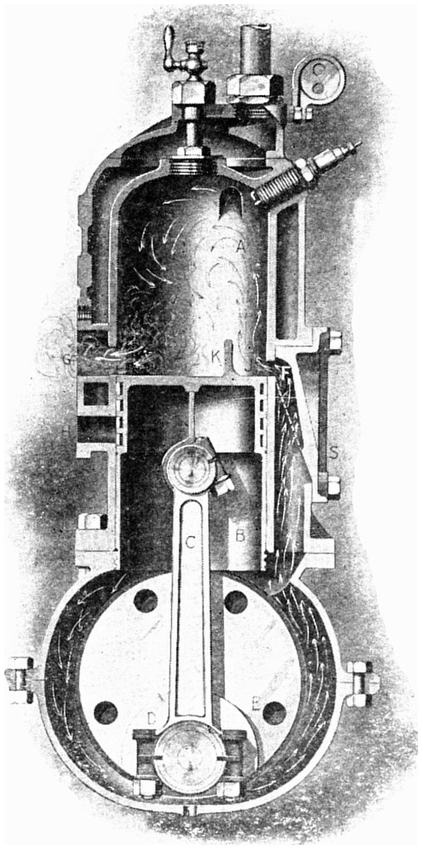
It is called a Two-stroke Cycle Motor,
so named because it combines in two strokes the
series of changes ordinarily accomplished in four
in the four-stroke cycle type. Its operation may
be seen by referring to the accompanying diagrams.
It is first assumed that the engine is being
turned over by hand in the direction indicated
by the arrow. You will note that as the piston
moves up it will uncover a port (H), allowing the
gasoline vapor from the mixing chamber to enter
the crank case. As soon as the piston moves down
again, a port (J) will be opened, allowing the
mixture which has just been compressed to rush
through a “by-pass” (F), into the “combustion
chamber,” or upper part of the cylinder. Now,
as the piston moves up again on the next stroke,
this charge is compressed still more, then as the
piston reaches its uppermost position the charge
is ignited and the engine begins to work under its
own power. The gases continue to act on the
piston until nearly the end of the stroke is reached,
when you will notice, by referring to the drawing,
the exhaust port (G) is passed. At this point the
burned gases rush out into the air. You will also
notice that in order to aid the discharge and fill
the cylinder again, as the piston travels a little
farther down, the inlet port will be again uncovered,
and the next charge, which has meanwhile
been taken into the crank case and compressed,
will enter the cylinder, forcing the exhaust gases out.
Fig. 40.
In order to prevent the vapor which has
just entered the cylinder from traveling straight
across and out through the exhaust port, thus
wasting a portion of the fuel, a “baffle plate” (K)
is cast on top of the piston which deflects the gases
toward the top of the combustion chamber, producing
a sort of whirling action which tends to
scavenge the cylinder most thoroughly. In order
to prevent the burning gases from traveling back
into the crank case and igniting the gas there, thus
producing a “back explosion,” a wire gauze (S)
is placed in the “by-pass.” You will note that
this type of motor has no valves, no cams and no
cam shaft, in fact, its simplicity is such that it
practically cannot get out of adjustment. It
therefore is a form of gas engine which as soon
as engineers are able to educate the public to its
peculiarities bids fair to become as popular and
practical as the four-stroke cycle.
A bigger and more comprehensive work
on the same subject.
“The How and Why of the Automobile”
Did you ever read a
book which gave you
just the information
you wanted without being
compelled to go through
page after page of introduction
and history?
¶ Did you ever talk to a
man who came over on
your side of the fence and
talked WITH you and not
AT you—who explained
things in such a way that
you laughed at yourself afterwards for not understanding the subject
before—it was really so simple?
¶ Do you remember when you used to study by outlines—how difficult
problems unfolded themselves—how the logical sequence of facts seemed
to make what you expected to find hard, readily understandable?
¶ Do you remember the innumerable times you have said to yourself
“If I only had somebody here to explain things—someone who would go
through this proposition with me until I understood it—someone who would
use homely and familiar examples to explain things, instead of talking over
my head by using technical terms?”
¶ The author realized all these difficulties himself, because he has been
through it all. Not only that, but his experience as an instructor of a
large motor school taught him the way to explain the various parts of a
motor vehicle in simple language, so that even the boy of fifteen could
understand and appreciate them.
¶ For instance, did you ever think that the physician uses a form of carburetor
whenever he gives chloroform or ether—do you realize that a
shotgun is a form of gas engine whose action is almost identical with that
of an automobile motor?
¶ Do you want to know what a sliding gear transmission is—explained in
such simple language that anyone can understand it?
¶ Would you like to see what’s inside of an automobile engine—would you
like to know the name of every part—be able to talk intelligently about
it and be your own mechanic—tell your chauffeur what to do—know when he
is bluffing you?
¶ In a word, would you like to know all about a motor car—how it works—how
to drive it and how to take care of it? Then subscribe for a copy of
“THE HOW AND WHY OF THE AUTOMOBILE”
By FAY L. FAUROTE PRICE, $1.00 PREPAID
Don’t delay—send in your order to-day. Get the complete story of a motor
car—the advanced course of which the book you have just finished is only
the beginning.
Address, Motor Text Book Dept. ROBERT SMITH PTG. CO., Lansing, Mich., U. S. A.
“THE HOW AND WHY OF THE AUTOMOBILE”
A book of practical information for seekers after the fundamental facts
regarding the gasoline engine and its application to the motor car.
Interesting and instructive to both the beginner and the expert—the
former for information, the latter for reference.
Written by Fay L. Faurote, B. S. (M. E.), for five years closely associated
with the Experimental Department of a pioneer automobile factory, for
two years instructor in the Detroit Motor School.
The book, which is handsomely bound in full cloth, printed on high-grade
enameled paper, contains over 200 pages and 250 illustrations and
covers the following subjects:
CONTENTS
General Theory of Gas Engines—Simple explanation of cycle—The
four-stroke cycle—The two-stroke cycle—Advantages and disadvantages
of each.
Motor Design—Cylinder, what it is and its use. Valves, mechanical
and automatic—Forms of valves—Valve timing and its influence on the
motor—Valve grinding, how to do it—Valve nomenclature. Crank
Case—The construction Bearings—Accessibility—Working parts—Uses.
A crank case oiling system. Crank Shafts—What they are—One, two,
four and six-cylinder crank shafts—Crank case diagram, showing
instantly conditions in all cylinders—Diagram showing firing points
and sequence of same. Connecting Rods—Construction and material—Bearings
and lubrication. Pistons—Piston rings—Piston pins.
The Carburetor—A very simple explanation of carburetion—The mixing
valve—A few of the first types—Some of the modern carburetors—Foreign
carburetors.
Ignition—The make and break system—A simple explanation of the
apparatus used. The Jump Spark System—Electrical units. Sources
of Electricity—The dry cell—The storage cell—Dynamos and magnetos—The
spark coil—Commutators and timing devices—Spark plugs—Wiring
diagrams.
Cooling System—Air Cooling.Water Cooling—Direction of circulation—Radiators—Water
pumps—Fans—Anti-freezing solutions.
The Transmission—Reason for and use of transmission. Simple
Explanation of Action—Individual clutch type—The sliding gear—The
three speed progressive—The three speed selective—The four speed
selective—Planetary gear—Friction drive.
Methods of Driving—Single chain drive—Double chain drive—Bevel
gear drive.
Running Gear—Front Axle—Construction of—Steering Gear. Rear
Axle—Differential gear—The live axle—The dead axle—Wheel construction—Bearings.
Horse Power Determinations—Engine testing—Indicated horse
power—Brake horse power—Mechanical and heat efficiency—Road
testing.
What a Prominent Trade Paper Says About It.
A Handbook of Practical Value—The latest addition to the
popular type of automobile handbook. “The How and Why of the Automobile,”
by Fay L. Faurote, fulfills what its author has set himself to
achieve, namely, to present a plain, easily understood description of the
modern automobile. Assuming that his reader knows nothing about the
subject, the author introduces the automobile in as simple and untechnical
a manner as possible. The entire field is covered and covered so completely
that the work can be recommended as a handbook for beginners or those with
only a limited knowledge of this subject.—Automobile, April 18.
Send in your order at once—don’t delay. The price is $1.00 postage pre-paid,
and the address is
Motor Text Book Dept., ROBERT SMITH PTG. CO., Lansing, Mich., U. S. A.
Punctuation, hyphenation, and spelling were made
consistent when a predominant preference was found
in the original book; otherwise they were not changed.
Simple typographical errors were corrected; unbalanced
quotation marks were remedied when the change was
obvious, and otherwise left unbalanced.
Illustrations in this eBook are shown as close
as possible to their original positions in the
printed book, so several of them actually are
mid-paragraph. This was done because some of
them are referenced only by their content,
not by their names.
The index was not in good alphabetical order;
Transcriber re-sorted it. It was not checked
for correct page references.